HMR-KK03の問題点
・電池残量の監視を行うように作られていない.
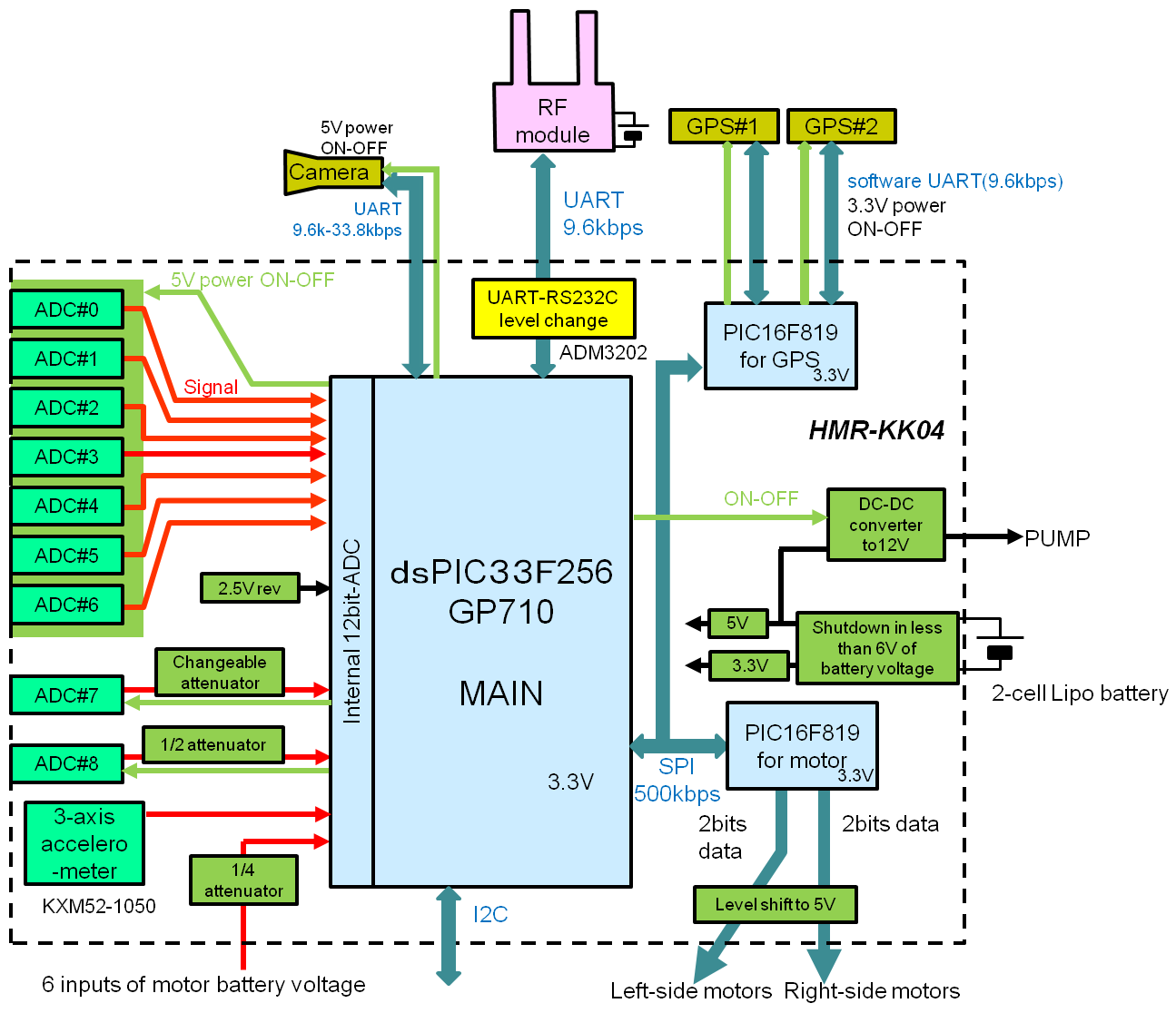
このため,HMR-KK04を作成した.基本的にHMR-KK03から大きな変更はない.ただし冗長な機能を削除した.またカメラモジュールの変更によりカメラへの供給電源を5Vに変更した.
| Function | Pin | Remarks |
| In-circuit programming | PGEC2, PGED2 | To ICD |
| I2C communication | I2C1 | 1ch |
| SPI communication | SPI2 | 2ch |
| Selection of GPS PIC | G9 | To SS of GPS PIC |
| Selection of Motor PIC | C4 | To SS of motor PIC |
| UART ch | ||
| Communication with RF module | UART1 | 1ch |
| Communication with CAMERA | UART2 | 2ch |
| LED | ||
| LED red | A2 | Light in H |
| LED yellow | A3 | Light in H |
| Power switch | ||
| Camera | B13 | ON in H |
| I2C Switch (I2C1) | F8 | ON in H |
| PUMP | D15 | ON in H |
| ADC #00-##06 | A0 | ON in H |
| ADC #07 | B12 | ON in H |
| ADC #08 | B14 | ON in H |
| ADC | ||
| ADC #00 | AN20 | PWR SW A0 |
| ADC #01 | AN21 | PWR SW A0 |
| ADC #02 | AN5 | PWR SW A0 |
| ADC #03 | AN4 | PWR SW A0 |
| ADC #04 | AN3 | PWR SW A0 |
| ADC #05 | AN2 | PWR SW A0 |
| ADC #06 | AN1 | PWR SW A0 |
| ADC #07 (changeable att) | AN0 | PWR SW B12 |
| ADC #08 (1/2 att for CO2 sensor) | AN6 | PWR SW B14 |
| Battery voltage RR (1/4 att) | AN17 | - |
| Battery voltage RC (1/4 att) | AN18 | - |
| Battery voltage RF (1/4 att) | AN16 | - |
| Battery voltage LR (1/4 att) | AN24 | - |
| Battery voltage LC (1/4 att) | AN26 | - |
| Battery voltage LF (1/4 att) | AN25 | - |
| Acceleromete X-axis | AN27 | Vref+ = Vdd |
| Acceleromete Y-axis | AN28 | Vref+ = Vdd |
| Acceleromete Z-axis | AN31 | Vref+ = Vdd |
NOTE
GPIO pins of B11 and B15 must be set as INPUT and are unusable.
ADC of the accelerometer outputs must be done as Vref+ = Vdd (3.3V).
| Function | Pin |
| Rx to GPS#0 | A0 |
| Tx to GPS#0 | A1 |
| PWR SW of GPS#0 (Turn on in H) | A7 |
| Rx to GPS#1 | A2 |
| Tx to GPS#1 | A3 |
| PWR SW of GPS#1 (Turn on in H) | A4 |
| Function | Pin |
| Right motor | A0, A1 |
| Right motor SW (Active in L) | A7 |
| Left motor | A2 A,3 |
| Left motor SW (Active in L) | A4 |
Mobile Sensor for Volcanic Observation "HOMURA"